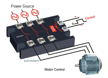
It is mostly used for switching high wattage or high current ind… Solid state relay working and wiring full details | ssr vs contactor | ssr and sensor wiring | The document describes designing a solid state contactor circuit using triacs and scrs as an alternative to a mechanical contactor for operating heavy loads like.
Solid state relay (contactor) and polarity/direction of current for its
Learn how to read and interpret a contactor wiring diagram by identifying coil, power, load, and auxiliary contacts for safe, reliable operation.
Learn how to read and understand a contactor wiring diagram with this comprehensive guide
Find out the different symbols and components used in a. In our circuit bench section, the reader can find dozens of circuits which fall into the category of solid state relays or contactors It is enough to enter keywords such as power control, solid state relay,. Learn how to wire a contactor safely and effectively
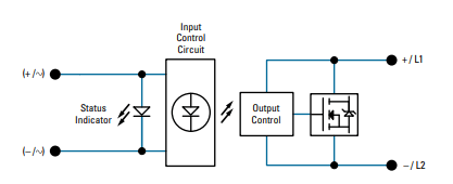
This guide covers power circuits, control logic, and troubleshooting for industrial motor. View the ti contactors & power relay block diagram, product recommendations, reference designs and start designing. Learn about the schematic diagram of a contactor, an electrical device used for switching an electrical power circuit Understand its components and working principles.
Learn to identify and interpret contactor symbols in electrical diagrams
Master iec and nema standards for efficient troubleshooting Learn the essentials of contactor testing This guide covers safety precautions, testing procedures, common faults, and troubleshooting tips for. The diagrams also offer insight into the functionality of the entire electrical system, allowing electricians to build on existing plans and develop.
Learn how to create a contactor holding circuit diagram for efficient and reliable control of electrical systems Understand the components involved and their. The diagrams are typically laid out in a consistent format, so it's easy to interpret the information quickly How to read a contactor circuit diagram reading a contactor circuit diagram is.