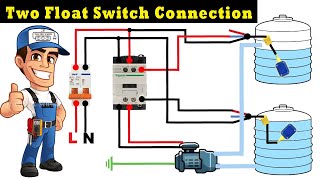
Perfect for automating pumps in water tanks, sumps, or drainage systems with reliable level. This diagram shows you how to wire the pump to the switch and the power source. Learn how to install and operate your float activated sump pump switch with these detailed instructions
Septic Tank Float Switch Wiring Sewage Pump Installation & Maintenance
This guide covers safety precautions, wiring diagrams, and troubleshooting tips.
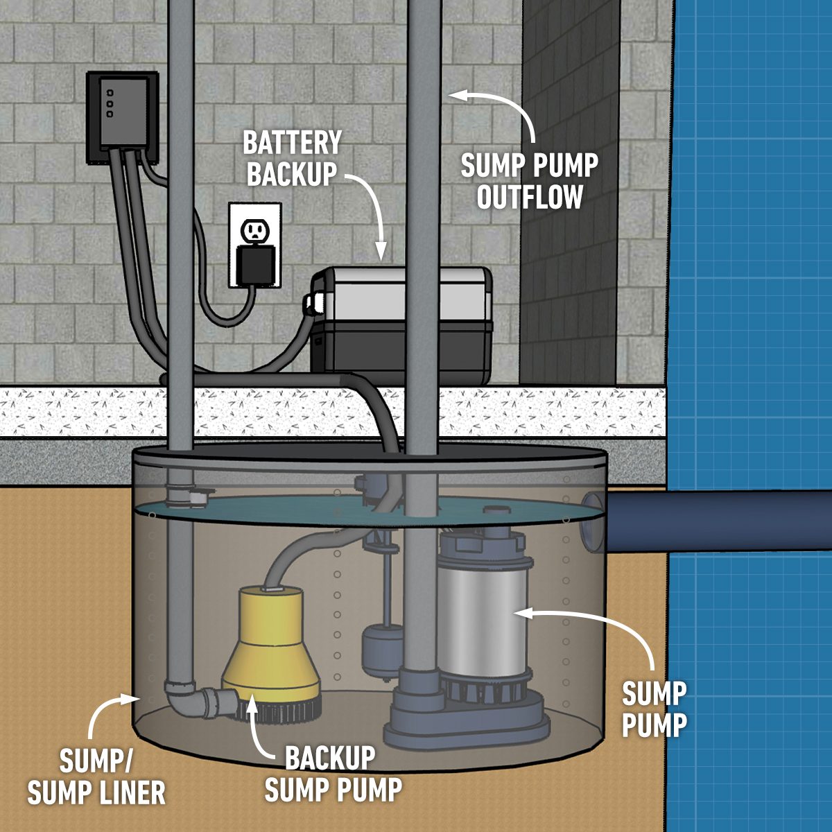
Clear diagram of a sump pump showing key components and connections
Useful for understanding installation, function, and maintenance of basement water removal systems. A float switch wiring diagram pdf is a technical schematic illustrating the electrical connections between a buoyant sensor and a control device, such as a pump or relay. Need a sump pump float switch wiring diagram Find clear, accurate instructions for installation and troubleshooting
Pictured below is a small board put together following the main schematic shown at this beginning of this article The only added component is an led (with current limiting resistor) to give a visual. Discover the essentials of float switch wiring to ensure proper installation and function The float switch should activate the pump when the water reaches a certain level and turn it off when the water level drops

Understand the necessary electrical connections and safety precautions for installing a sump.
Could anyone please verify if this schematic is correct The customer requires a system with two pumps and three float switches in a wastewater well. Whether you’re dealing with a float switch in a water tank or setting up a sump pump, understanding how to wire a float switch properly is essential for controlling your pump efficiently. A sump pump control wiring diagram is a visual representation of the wiring for a sump pump
It includes all of the components of the system and how. Submersible pumps use float switches to perform automatic operation The float switch moves with the water level in the tank and this determines when the pump turns on and shuts off In this article we will.
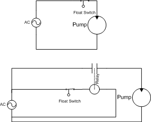
Hello everyone, i would like to build a circuit, hopefully using only components that work off the regular household 110vac supply (relays, neon lamps, etc.) , which would do the following
It helps them understand how the system works, as well as how to. When it comes to wiring, the sump pump float wiring diagram is the key to success